|
The pistons, rings, pins, rods and related parts were also balanced. The flywheels were statically balanced at 60%. Then the pinion shaft was installed; the nut was lapped flat using 4(X) paper on glass. The pinion was torqued to 275 foot-pounds. The process was repeated on the sprocket shaft, which was torqued to 400 foot-pounds, with 350 foot-pounds on the crank pin nuts. When setting up the pinion shaft hearings we used the one-piece caged pinion bearing as opposed to the multiple-piece caged hearing for a better fit. The one piece appears to carry more of a straight load, has less rotating parts and less area for friction due to less pieces. The sprocket shaft bearing was heated slightly on the inner race with map gas to ease in its installation. It was allowed to cool then was lubricated and installed in the left case half. The outer hearing was installed and the end play checked. The seal was installed so that it was cup shaped, which is not how you would normally see it. This keeps the primary oil out of the engine. The pinion bearing was lubricated and the right case half installed and torqued to 25 foot-pounds using the Harley-Davidson pattern. While the flywheels were being set up the cylinders were being prepared for boring and honing. Special aluminum torque plates were used along with gaskets and torqued to 25 foot-pounds, then 35 and finally, 45 foot-pounds. They were bored and then honed using a AN500 Sunnen hone and finished to .0001 of final size and then plateau brush finished, which is a 280 grit. After the cylinders are honed and cleaned, the ring end gap was set. The top ring was set up with .006 per inch of bore and the second ring was set up with .005 per inch. The pistons with rings installed were put on the rods and the cylinders installed and secured. A dial indicator was installed and measured top dead center of the front piston. A degree wheel was installed and the engine was then turned backwards (clockwise) and the 25-degree timing mark installed. This turned out to be the same as our calculations of .281 using the dial indicator. The same procedure was performed on the rear cylinder. The oil pump had the check ball seat reestablished using a special cutter before installation.
|
|
 |
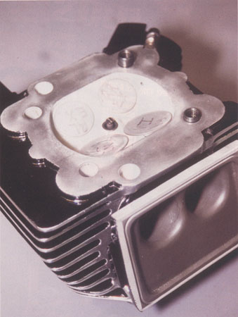 How trick is this? Center plug, four valves, andprecision porting to boot! |
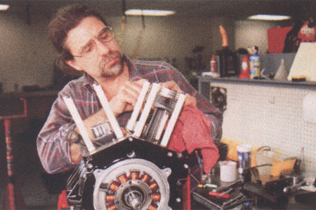
Protecting sleeves on cylinder studs savethe piston skirts from getting nicked during assembly. |
|
 |
|
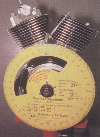
Camshaft specs are checked with thedegree wheel. |
|
 |
|
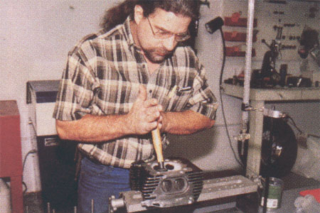
Lapping all valves ensures optimum fit. |
|